Skip to main content Skip to search

Posts by admin

Planning Models for Inverter-Based Resources

By Francis Luces, Ric Austria, Cherry Bautista

(Pterra has provided support to developers on most aspects of grid interconnection, including pre-feasibility/site assessment, modeling, interconnection, and engineering design studies.)

In today’s rapidly evolving energy landscape, the reliability and efficiency of the power grid are more crucial than ever. An increasing penetration of inverter-based resources (IBR) to meet clean energy targets will also mean an IBR-dominated dynamic behavior of power systems. It is extremely important that a usable power system model representation of IBR, conventional machines, loads, and other components is submitted to utilities to support the analysis of the reliability of the transmission system.

Our Services to Meet Planning Model Submissions

Pterra offers modeling and reporting services to help conventional, or IBR plant owners comply with ISO/RTO or utility-specific interconnection application requirements and/or regulatory-mandated model submission guidelines:

Phasor-based Steady-State and Dynamic Models

PSS/E is the program used by most utilities and ISOs based in the East Coast while PSLF is used by the Western Region. Regardless of which software is being used, a usable phasor-based steady-state and dynamic model of the Plant is required for submission to aid planning engineers in their interconnection or network studies.

Oftentimes, IBRs are represented using generic dynamic models in these two well-known programs due to their simplicity. These models offer flexibility and low maintenance on larger database sets, but it is important to recognize that they have limitations. When standard models do not reflect the actual behavior of the equipment, a user-defined model (UDM) should be used and must be properly parametrized according to Project specifications.

Electromagnetic Transient (EMT) Models

Traditional use cases for electromagnetic transient simulations were insulation design, surge protection, controller design, and equipment rating adequacy studies. In the studies of IBR interconnection, EMT modeling and simulations are now needed to verify responses of IBR such as fault ride-through, P/Q priority, voltage and frequency step, phase angle jump, among others. Unlike phasor-based models, the EMT model is the closest representation of the actual equipment and controls present in the field, thus considered a high-fidelity model for system studies. ISO/RTOs have recognized the need to include PSCAD or EMTP-RV model submissions of IBRs to augment offline power system studies that were traditionally performed by phasor-based simulations.

Model Benchmarking and Validation

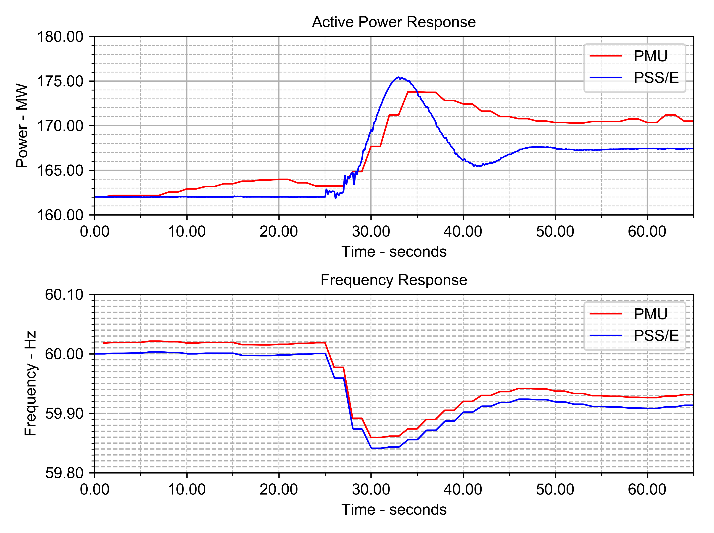
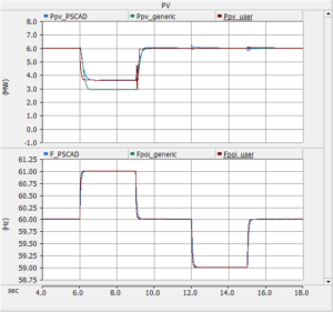
Model benchmarking is an exercise to compare model responses across different software platforms. Typically, the simulation results obtained from PSS/E and PSCAD are overlaid in one plot to allow comparison. This approach helps ISO/RTO engineers to understand model behavior and helps planning engineers to create and make better engineering solutions. The model validation is also a benchmarking effort which focuses on comparing inverter-level EMT model response against field recordings, such as those obtained from hardware in-the loop (HIL) simulations or actual measurements from grid events.


The table below shows the summary of model requirements and the corresponding references stating such requirements.

ISO/RTO/Utility PSSE Requirements PSCAD Requirements Reference Document
ISO‑NE Power Flow Model EMT Model ISO-NE Planning Procedure 5-6
Standard Model accepted
User-Defined Model not accepted
NYISO Power Flow Model EMT Model Modeling Guideline for NYISO Interconnection Data

NYISO Electromagnetic Transient (EMT) Modeling Guideline

Standard Model accepted
User-Defined Model accepted
PJM Power Flow Model Developers wil be noted during TC2 Phase if a PSCAD model is needed PJM Dynamic Model Development Guidelines for Interconnection Analysis
Standard Model accepted
User-Defined Model accepted
MISO Power Flow Model EMT Model MISO Planning Modeling Manual v4.4
Standard Model accepted PSCAD Model Requirements Supplier Checklist
User-Defined Model accepted BPM 015 – Generation Interconnection
SPP Power Flow Model EMT Model  SPP EMT Model Requirements
Standard Model accepted
User-Defined Model accepted
ERCOT Collector Power Flow Template EMT Model Template ERCOT Dynamics Working Group Procedure Manual
Power Flow Model (aggregate) EMT Model
Dynamics Model Template
Standard Model accepted
User-Defined Model accepted
SOCO Power Flow Model EMT Model SOCO Model Submittal Requirements for Transmission Connected IBRs
Standard Model accepted
User-Defined Model accepted
TVA Power Flow EMT Model TVA Modeling Requirements
Standard Model accepted
User-Defined Model accepted
HECO Power Flow EMT Model Hawaiian Electric Facility Technical Model Requirements and Review Process
Standard Model accepted
User-Defined Model accepted

Model Quality Testing

Model quality testing for IBRs in PSSE and PSCAD are a set of prescribed tests by utilities to ensure the accuracy and reliability of models submitted. Typically, the tests may include flat run, ringdown, ride-through, small step inputs on voltage and frequency controllers, and short-circuit ratio () calculations. For projects that will provide grid services or as part of power purchase agreement (PPA), additional tests such as deadband, high and low frequency disturbance, or nighttime reactive power capability are called for to demonstrate capability and compliance. Finally, new model tests such as loss of last synchronous machine (LLSM), black start capability, interaction, and phase angle jumps are being required for projects that are equipped with grid forming (GFM) control topologies such as virtual synchronous machine (VSM) or droop-based control.

NERC MOD Compliance

NERC issues a set of reliability standards, known as (Modeling, Data, and Analysis) Standards, that aim to ensure consistent modeling data reporting and validation of equipment owned by Generator Owners (GO) or Load Serving Entities (LSE). The MOD standards are:

  • MOD-032-1 — Data for Power System Modeling and Analysis
  • MOD-033-2 — Steady-State and Dynamic System Model Validation
  • MOD-026-1 — Verification of Models and Data for Generator Excitation Control System or Plant Volt/Var Control Functions
  • MOD-027-1 — Verification of Models and Data for Turbine/Governor and Load Control or Active Power/Frequency Control Functions

Typically, Transmission Planners (TP) or Planning Coordinators (PC) sends a notification to GOs and LSE for updating of power system data, model submissions, and reports of model validation against field measurements. The MOD compliance will require modeling and simulations of the Plant using phasor-based programs which can be performed by plant owners or oftentimes, third-party consultants like Pterra.

On the Model Accuracy and Usability

With the release of FERC Order 901, the accuracy of models and their usability is more important than ever to address existing and potential reliability issues associated with IBR interconnections. Our modeling efforts focus on the following key points to deliver an accurate and usable model:

  1. The models can be parametrized according to Project, and the model response is consistent with the field measurements.
  2. The parameters (e.g. control gains) applied are within the acceptable range and can be equally applied in the field.
  3. The models comply with ISO/RTO or utility-specific model testing requirements and quality assurance.
  4. The models used are not in the list of unacceptable models and represent the required control features, deadbands, and protection settings as prescribed by NERC.

Conclusions

Increasing IBRs applications results in backlogs on interconnection queues but model accuracy and usability cannot be comprised. While planning model submissions are only a small subset of a long list of interconnection application requirements, its impact to ensuring system reliability is significant.

Pterra, as a consultant, endeavors to maintain the key points mentioned above and establish collaborations with inverter original equipment manufacturers (OEM), utilities, and project developers to meet and deliver accurate, usable, and high-quality power system models.

Read more

Resolving PJM’s Cost Allocation Dispute

By Ric Austria, Cherry Bautista

In a significant move for the U.S. energy sector, a proposed settlement filed with the Federal Energy Regulatory Commission (FERC) promises to resolve a long-standing dispute over how costs for critical transmission upgrades are shared within PJM Interconnection, one of the nation’s largest regional grid operators. This agreement, detailed in filings from the Indicated PJM Transmission Owners (ITOs), Long Island Power Authority (LIPA), Neptune Regional Transmission System, LLC, and supported by technical analysis from Pterra, addresses fairness in cost allocation while paving the way for a more reliable grid. Here’s a deep dive into what this settlement means and why it matters.

The Heart of the Dispute

The conflict, unfolding over four years, in FERC Docket Nos. EL21-39-000 and ER22-1606-000, centers on PJM’s Solution-Based Distribution Factor (DFAX) methodology, which determines how costs for Required Transmission Enhancements (RTEP projects) are allocated across its 21 zones. In 2020, LIPA and Neptune challenged two aspects of this system as unjust:

  • 1% De Minimis Threshold: Zones with a distribution factor below 1% are exempt from costs, often leaving smaller entities like Merchant Transmission Facilities (MTFs)—such as Neptune’s transmission line—shouldering disproportionate burdens compared to larger zones like PSEG (11,000 MW peak load vs. Neptune’s 685 MW).
  • Netting Procedure: By offsetting positive and negative energy flows, this method disadvantages MTFs, which, as single-node entities, can’t benefit from netting, unlike networked zones.

These issues sparked concerns about fairness, with LIPA and Neptune arguing that the methodology violated the “beneficiary pays” principle, unfairly burdening smaller players. A 2022 D.C. Circuit ruling in a related case (Consolidated Edison Co. of N.Y., Inc. v. FERC) echoed these concerns, finding that assigning hefty costs to small MTFs while sparing larger zones defied cost causation principles.

Adding to the debate, a 2021 affidavit by Pterra’s Ric Austria, analyzed an alternative nodal DFAX approach without netting or the 1% threshold. Using PJM data for upgrades in non-PSEG zones (e.g., projects b0487, b0489), Pterra showed that applying MW usage thresholds allocated costs more equitably, reducing assignments to zones with minimal usage. Pterra’s findings underscored the need for reform, setting the stage for settlement talks.

The Proposed Settlement: A Balanced Solution

Filed on February 14, 2025, the settlement offers a pragmatic fix to these issues through targeted revisions to PJM’s Tariff Schedule 12. Here’s what it entails:

Zonal Integration for MTFs

MTFs with Firm Transmission Withdrawal Rights (FTWRs), like Neptune, will no longer be treated as standalone zones. Instead, they’ll be integrated into their interconnected zone’s load—for instance, Neptune’s 685 MW FTWRs join JCPL’s 6,200 MW peak load, sharing ~10% of JCPL’s DFAX costs. This mirrors existing practices, like PSEG/RECO, where smaller loads are integrated for fairness. Integration applies only to DFAX-based upgrades, with provisions to end if FTWRs are relinquished or zone boundaries shift significantly.

No Host Zone Exclusion

Building on a 2022 proposal, host zones (where transmission upgrades are built) are exempt from the 1% de minimis threshold, ensuring they bear costs based on their DFAX value, even below 1%. This reflects both direct and indirect benefits, with refinements to use physical location data for projects after December 11, 2023, improving accuracy over earlier ownership-based identifiers.

Retroactive and Prospective Fixes

The changes apply back to December 31, 2020, with PJM recalculating costs and issuing refunds or surcharges within 180 days of FERC approval. Going forward, annual RTEP updates will reflect the new methodology.

Safeguards and Clarity

The settlement ensures Neptune remains exempt from the State Agreement Approach project costs and prevents parties from undermining the agreement in other forums, fostering stability.

Why It Works

The settlement is a win for fairness and efficiency, delivering several key benefits:

  • Ending a Four-Year Feud: By resolving contentious litigation, it saves time and resources, aligning with FERC’s preference for negotiated solutions.
  • Fairer Cost Sharing: Zonal integration lets MTFs benefit from netting and de minimis exemptions, addressing Pterra’s call for usage-based equity. The host zone exclusion ensures no zone escapes responsibility for projects it benefits from.
  • Minimal Disruption: Data shows only a 1% cost shift ($114.81 million), with zones like JCPL and PSEG absorbing modest increases while Neptune sees significant relief ($114.80 million less), keeping PJM’s system stable.
  • Robust Evidence: Pterra’s analysis, using PJM’s power flow models, validated that a usage-based approach reduces allocations to marginally impacted zones, informing the settlement’s design.

A Boost for the Energy Future

By clearing cost allocation hurdles, the settlement ensures timely RTEP projects.

The Big Picture

This settlement isn’t just about numbers; it’s about building a grid that’s ready for tomorrow. By fixing how costs are shared, it supports the infrastructure needed for a cleaner, more resilient energy system. As FERC reviews this proposal, the stakes are clear: a fairer PJM grid today means a stronger energy future for all.


Read more

Pterra at IEEE TPEC 2025

Meet Pterra’s Francis Luces & Yifu Li at Texas A&M University during the IEEE TPEC 2025 event on Feb 10-11, 2025! Pterra will be presenting our technical paper, “dqBOT: An Automation Tool for Benchmarking Dynamic Quality in Generator Interconnections.”

We look forward to sharing our insights and engaging with industry professionals at this prestigious conference. Stay tuned for more details!

Abstract—In response to the recent Federal Energy Regulatory Commission (FERC) Order 2023, which mandates the use of cluster studies to expedite the interconnection process, Independent System Operators (ISOs) and Regional Transmission Organizations (RTOs) are now confronted with the challenge of managing hundreds of interconnection applications simultaneously. FERC also requires interconnection customers submitting nonsynchronous generator facilities, such as inverter-based resources (IBRs), to provide the root-mean-square (RMS) positive sequence dynamic model and the validated electromagnetic transient (EMT) model. These requirements, aimed at ensuring model accuracy across various scenarios—such as reactive power limits, frequency and voltage changes, fault ride through, and grid stiffness—pose a time-consuming and error-prone challenge for engineers. This paper proposed an automation tool, dqBOT, developed to streamline the testing process by automating procedures, reducing misinterpretation, and enabling engineers to focus more on analysis. dqBOT has been validated against the established tools of the Electric Reliability Council of Texas (ERCOT), demonstrating qualified results. Additionally, dqBOT can be applied in other ISOs/RTOs to meet their testing requirements. It can also automatically compare the results between RMS and EMT models, accelerating the tuning process of the RMS model.

The full paper is available upon request for our client, please contact your project manager or info@pterra.us

Read more

The Transmission Planning Process

By Ric Austria

(This Blog presents the salient points of a presentation made to the North Carolina Utilities Commission in 2022 on the subject. A redacted version of the presentation can be found at this link. The author is Executive Principal at Pterra Consulting, and has conducted courses on Transmission Planning and related topics for over 40 years. He pioneered the concept of planning for Robustness and Flexibility, which are discussed further in this Blog.)


Transmission planning is changing. That is to say, it has always been changing, evolving to adapt to the changing electric supply and delivery landscape. From the early days of PURPA to deregulation to the development of energy markets to the first wind farms and on to zero emissions target portfolios, inverter-based resources, storage, offshore wind, high-voltage direct current (HVDC) transmission, distributed generation, data centers, and more, the building blocks for transmission plans have been constantly changing. In parallel, the perceptions on the role of electric energy in global commerce and livelihood, the desire for a greener energy mix, the acceptable costs for maintaining reliability and the aim for sustainability and resilience have likewise been factors for change. Furthermore, the end-game calls for electric transmission and the “ugly” structures that enable the transfer of potent energy have grown louder: that the future is in microgrids or beamed transmission, or portable energy sources, and other non-wires alternatives, and hence, that we need those towers and poles less and less, and eventually not at all. Perhaps, but not just yet, not by far. For the moment, whether that be a brief one or a longer timeframe, we still need to plan for transmission. To do so, we need to have a proper process for transmission planning, one that is appropriate for the present time to address the needs and objectives that we value today.

Recently, the prime drivers for change in the USA are federal and state mandates for improved planning, use and management of transmission systems. FERC’s initiative for an improved planning process to state mandates for various targets on solar, storage, offshore, mini-nuclear, and the like, are now necessary and important considerations in planning. (The FERC NOPR and examples from New York, New Jersey and California are discussed in more detail in the linked slide deck.)  Significant elements of these mandates, to name a few, are: “right-sizing” replacement transmission lines, consideration of advanced technologies, coordinated planning across states and regions, impact of distributed generation, unified planning models, and public policy transmission needs. These considerations introduce significant, even game-changing and paradigm-shifting, factors in developing transmission plans. However, the desired attributes and features for such plans can still be generalized into the following three key characteristics:

  1. Long-term viewpoint. Transmission lines have 40-plus years of effective lifetimes and plans need to account for at least a significant portion of that period.
  2. Plans need to provide for a future transmission grid that maximizes the desired attributes, or, if stated from the orthogonal perspective, that poses the least regret.
  3. Because the future is uncertain, the plan needs to have a built-in roadmap that provides for alternate tracks for when less expected events take place.

And yet, there is more. While not yet widely accepted, there is a growing and insistent demand to design transmission systems, not based on a capacity model but on an energy model. The capacity model for the transmission system is embodied in the so-called Umbrella Principle, which states that “if an electric grid is able to reliably withstand extreme conditions such as high peak demand, and uncustomary climate and/or market conditions, then it can reliably weather any other operating condition.” The thin membrane represented by the fabric of the umbrella defines the capacity boundary within which the grid operates reliably. The capacity model leads to transmission plans that are defined by extreme conditions of use. Energy planning, in contrast, relies on the application of advanced technology and non-wires alternatives, such as dynamic line rating, programmable storage, power flow controllers and advanced distribution management systems, among others, to mitigate extreme grid operating conditions. The least-cost objective of energy planning is thus modern technologies and programs in combination with transmission infrastructure plans. Energy-based transmission planning is starting to appear in the industry such as in the energy headroom measurements posted by New York utilities and the Energy Storage NOPR released by FERC.

Needless to say, there is much in flux in transmission planning processes. Some of the best practices that we can note are:

  • Coordinated planning involving more stakeholders, including state and local agencies, generation developers, customer groups, banks, regulatory agencies, research and development institutes, taxation authorities, etc. While not all parties can participate in the detailed simulation and modeling aspect of transmission planning, their input and oversight enable a broader perspective than the traditional centralized planning process.
  • Involvement, if not actual integration, of distribution planning. A significant portion of new and planned energy resources are smaller scale, interconnecting at distribution voltages. The issues of net metering, backfeed and upramp/downramp capacities have a significant impact on transmission systems.
  • Broader study sets. As noted earlier in this Blog, system use is changing. Even when still applying the Umbrella Principle, the number of unique conditions for grid stress has increased, necessitating more models and more simulations of future conditions.
  • Directed renewable development. Two efforts to attract the development of renewables where existing and planned transmission capacity is or will be available are: (1) renewable energy zones, or REZ, where bulk transmission capacity is planned ahead of supply availability to attract developers, and (2) hosting capacity and energy headroom which identify where transmission headroom is limited and where utilities may garner regulatory support/approval to expand the transmission to attract future developers. Directed development reduces the uncertainty of planning for the future.
  • Formalized procedures to accept advanced technologies and programs as planning components. Several are ongoing, such as FERC’s efforts to standardize dynamic line rating and utility efforts to use advanced distribution management to interconnect energy-only resources.

The link includes a sample outline for a capacity-based transmission planning process. While this is perhaps still best practice for today, it is easy to envision drastic changes to the process as the broader considerations discussed in this Blog have noted.

Read more

Pterra at PSCAD UGM 2023

Introducing Our Principal Engineers’ Talk at PSCAD UGM 2023, Boston!


Join us at PSCAD UGM 2023 in Boston, where our Principal Engineers will unveil a compelling case study. A load break switch’s unexpected failure during a vital task led to an extended arcing event, triggering a single line-to-ground fault. Using PSCAD/EMTDC simulation, we examined the interrupter’s transient recovery voltage (TRV). In a restrike scenario, the transient current surged to 1000 A, and the peak line-to-ground voltage spiked to 2.20 p.u. Notably, the computed TRV reached 536 kV post-restrike, surpassing the interrupter’s 480 kV TRV capability rating.

This study highlights two key recommendations:

  1. Enhanced Operational Protocols: For interrupters without capacitive switching ratings, review and refine switching procedures.
  2. Empowering Line Charging Interruption: Explore interrupters with capacitive current interruption capabilities to handle unloaded transmission lines.

For the full slide set and deeper insights, contact us at info@pterra.us. Don’t miss this illuminating presentation shaping the future of power engineering!

Read more

Pterra Conducts Interconnection Assessment for New York Great Lakes Wind Energy Feasibility Study

In December 2022, the New York State Energy Research and Development Authority (NYSERDA) published a report on the Great Lakes Wind (GLW) energy feasibility based on a study conducted by the National Renewable Energy Laboratory (NREL), Advisian Worley Group, Brattle Group and Pterra Consulting.  This study (link to the full report) was intended to complement the options for renewable resources such as land-based wind, solar, hydro and offshore wind that would help meet New York’s renewable energy portfolio and decarbonization goals under the New York State Climate Act.

New York State is bounded by two of the Great Lakes, Lake Erie to the west and Lake Ontario to the north. The potential for developing fixed and floating wind turbines on the lakes using both existing and emerging technologies was the focus of the feasibility study. The study examined myriad issues, including environmental, maritime, economic, and social implications of wind energy areas in these bodies of freshwater and the potential contributions of offshore GLW projects.

Pterra’s role in the study (link to interconnection report) was to conduct a feasibility assessment for potential interconnections of GLW generation with the New York Bulk Power System (NYBPS). To perform the assessment, Pterra developed power flow models to represent the NYBPS in 2030 with an assumed renewable generation buildout.

To provide a measure of interconnection capacity, the capacity headroom definition and calculation method described in recent New York State Public Service Commission orders were selected. Potential points of interconnection (POIs) on the existing NYBPS substations located within 20 miles of either the Lake Erie or Lake Ontario shoreline were initially selected for analysis. These were filtered down to a few representative POIs for more detailed analysis. (Headroom represents the potential capability for GLW to interconnect; however, it also represents the capacity that is available to any other generation resource that may want to interconnect at the same POI. The nature of the NYISO market for any new generation is competitive and GLW is expected to compete with other resource development modeling analyses to utilize the available headroom.)

Lake Erie abuts the New York counties of Erie in the north and Chautauqua in the south. For Lake Erie GLW, the available POIs showed combined capacity headroom of 270 megawatts (MW) without transmission upgrades. Applying a set of simple transmission upgrades costing some $68.8 million can increase the Lake Erie total headroom capacity by 60 MW to 330 MW.

New York State has a longer shoreline along Lake Ontario compared to Lake Erie. Several New York State counties border the lake, including Niagara, Orleans, Monroe, Wayne, Cayuga, Oswego and Jefferson. For Lake Ontario GLW, several POIs in Monroe and Oswego counties showed solo headroom capacity in the range of 850 to 1100 MW without the need for transmission upgrades. At most, there is a total headroom capacity of up to 1140 MW for the Lake Ontario POIs. The total headroom capacity may be increased by 140 MW by implementing simple upgrades costing some $236.6m. In Jefferson County, the studied POIs showed no solo headroom capacity. Simple transmission upgrades costing at least $164.5 million may open about 50 MW of headroom capacity.

Pterra’s interconnection assessment found that there is some headroom capacity on the NYBPS for which GLW can compete for the delivery of energy to the grid. In order to access the POIs with headroom, other reliability issues relating to transient voltage, stability, short circuit, deliverability, transfer capability and higher-level contingencies would also need to be considered.

Read more

Benchmarking Phasor and EMT Models for Inverter-Based Energy Resources

By Francis Luces, Ric Austria

Power projects planning to participate in the wholesale market are required to undergo impact studies as part of the interconnection application process. The studies, as a minimum, evaluate the performance of the projects under instantaneous, steady-state and transient conditions. The timescales of phenomena and equipment studied are as illustrated in Figure 1.

In the specific case of transient studies, the impact of a proposed project on the voltage and frequency control capability of the overall grid is evaluated. Traditionally, it was sufficient to consider a timeframe of 0.5 to 10 Hz (10-100 msec) for a type of study known as transient stability. The computer models (and software, such as PSS/E and PSLF) used to conduct these studies are known as phasor-based models. These models capture phenomena limited to the target timeframe.

Read more

Network Equivalents for the Power System Engineer

By R. Austria, M. Gutierrez, F. Luces

Very popular pre-2000, when computer processing bandwidth was at a premium and engineers had more time to put together study information on the desktop (the wooden one, not the one filled with integrated circuits), equivalencing appears to have gone the way of the calculator, the clock and the calendar. Ok, so not quite, as the smartphone does not yet have an “equivalent” function. This will have to wait until analytical programs for power system analysis are made portable. But nonetheless, today’s power engineers will more readily go for the brute force approach of “model everything” rather than take the extra time and effort of creating a simplified model.

Read more

Technical Aspects of Battery Energy Storage Systems for Integration in Distribution Circuits in New York State

Pterra was engaged by the New York State (NYS) Department of Public Service (DPS) to provide some insight into technical issues associated with battery energy storage systems (BESS) interconnecting into distribution feeders. This work was part of ongoing support Pterra is providing to the NYSDPS on NYS Standard Interconnection Requirements (SIR) procedures.

Read more

System Impact Study for a Proposed Transmission Interconnection Project in New York

By R. Tapia, M. Gutierrez and M. Infantado

Introduction

Independent System Operators (ISO) constantly face the challenge of assessing the impact of facility additions to the power grid. They normally require a system impact study for any proposed interconnection of a large generating plant or transmission project. The purpose of this analytical study is to determine the potential adverse impacts of the interconnection of transmission facilities to a power system and whether it would cause any of the following:

  • Post-contingency thermal overloading on transmission lines and transformers,
  • Voltage criteria violations on substations,
  • Negative impact on the dynamic response of power system facilities,
  • Degradation on the transfer limit of transmission interfaces,
  • Increase in substation short circuit current that could possibly exceed the fault duty of existing circuit breakers.

The system impact study determines the impact of the proposed project by comparing simulation results of the case with the project in service against the case without the project. If adverse impacts were to be found, appropriate solutions to mitigate the violations would be required, except for the extreme contingency assessment which is performed for information purposes on issues such as avoidance of widespread load interruptions, uncontrolled cascading, and system blackouts among others.

Read more